Raspberry Pi using Scratch as HMI, involving wiringPi and Qt for programming and open source hardware boards from electronics.cat.
Boards used in the video :
Raspberry Pi : Raspberry Pi
set05_08 : 3Bpi - Level translator board for Raspberry Pi
set05_04 : Input Board
set05_02 : Relays Board
set01_04 : Inputs and Outputs (microswitch + LEDs)
Requirements :
- Qt4 tool chain installed on Raspberry Pi
- wiringPi installed on Raspberry Pi
- Connect reliable hardware to GPIO (be aware Raspberry Pi use 3.3V internally)
To compile Qt code using wiringPi on Raspberry Pi :
- Uncompress Qt code using wiringPi
- On the qtPi04 directory, type on the terminal :
qmake
make
To run this sample :
- Run Scratch and open Scratch’s code
- Type on terminal :
sudo ./qtPi04
pi@raspberrypi ~/code/wiringPi/qtPi04 $ sudo ./qtPi04
3Bpi + Raspberry Pi + Qt + wiringPi test program
TCP disconnected
Scratch cannot be connected through TCP <= If Scratch is not running
“xxxx1111″
pi@raspberrypi ~/code/wiringPi/qtPi04 $ sudo ./qtPi04
3Bpi + Raspberry Pi + Qt + wiringPi test program
TCP connected
Scratch connected through TCP <= If Scratch is running with Scratch’s code opened
“xxxx1111″
“xxxx1101″ <= When a switch is pressed
“sensor-update note 60 beats 0.4″
“broadcast “0×3E_SW1_pressed”"
“xxxx1111″
“sensor-update note 62 beats 0.4″
“broadcast “0×3E_SW1_unpressed”"
As a tip to understand how it is programmed this is a C code using wiringPi and this is its translation to C++ using Qt and wiringPi.
This post is a proof of concept using Raspberry Pi, wiringPi, 3Bpi and other OSHW boards.
wiringPi is a GPIO Interface library for the Raspberry Pi written by Gordon Hederson ( projects.drogon.net). It is designed to be familiar to people who have used the Arduino “wiring” system. And it is very friendly and convenient to use interfacing external boards to GPIO’s Raspberry Pi.
Video :
To compile the code having installed wiringPi on Raspberry Pi :
gcc wPi00.c -o wPi00 -lwiringPi
Boards used in the video :
Raspberry Pi : Raspberry Pi
set05_08 : 3Bpi - Level translator board for Raspberry Pi
set05_02 : Relays Board
set01_04 : Inputs and Outputs (microswitch + LEDs)
In this specific sample, 3Bpi is used as a connector translator among boards. Translation between 3.3V and 5V is not required to drive outputs .
wiringPi can use different pin numbering. To translate by default pin numbering to 3Bpi ports I have used this global variables :
uint8_t byP2wPiMaster[] = {19,20,15,16}, byP2wPiSlave[] = {20,19,16,15};
uint8_t byP3wPi[] = {18,17,1,11,10,12,13,14}; /* [0]:LSB, [7]:MSB*/
uint8_t byP4wPi[] = {9,8,5,6,4,2,3,7}; /* [0]:LSB, [7]:MSB*/
And to define which pins are output or input I have used this notation (In this sample all the pins modes are outputs) :
#define P3_SETUP 0×00 /* 0 : Output, 1 : Input*/
#define P4_SETUP 0×00 /* 0 : Output, 1 : Input*/
Using these constants to call pinMode() :
v3BpiP3pinMode(P3_SETUP);
v3BpiP4pinMode(P4_SETUP);
Some electronics.cat’s boards are using nibbles to read inputs and to write outputs (for instance set05_02 Relays Board or set05_04 Input Board). For this reason these functions have been created :
void v3BpiP3digitalWrite(uint8_t by){
v3BpiHighNibbleP3digitalWrite(by);
v3BpiLowNibbleP3digitalWrite(by);
}
void v3BpiP4digitalWrite(uint8_t by){
v3BpiHighNibbleP4digitalWrite(by);
v3BpiLowNibbleP4digitalWrite(by);
}
These functions call to digitalWrite().
Code of this proof of concept can be downloaded clicking on this link.
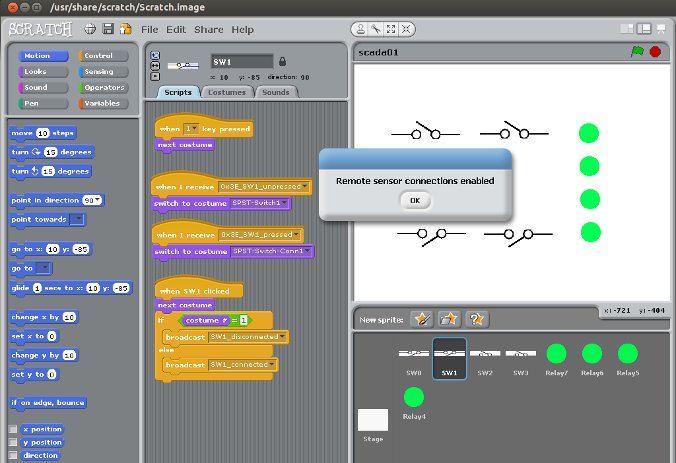
Simple Supervisory Control and Data Acquisition (SCADA) using Scratch and some open source hardware boards connected to a GNU/Linux Ubuntu computer using USB.
Boards used :
set01_05 : USB - RS232 TTL / TWI (I2C) translator
set03_03 : Digital Input / Output TWI (I2C) expander
set05_04 : Input Board
set05_02 : Relays Board
set01_04 : Inputs and Outputs (microswitch + LEDs)
Scratch should have remote sensor connections enabled. Once Scratch is running (it is acting as a TCP server), interface software (acting as a TCP client) can connect it.
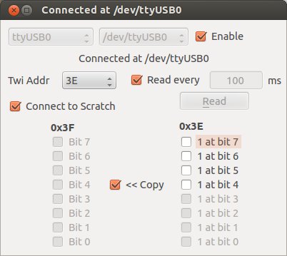
Interface between OSHW and Scratch :
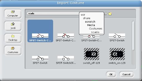
Scratch’s Import Costume dialog :